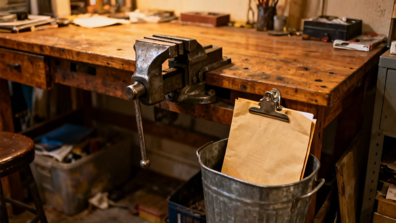
A tool list is on the back. The drawer has a different set. You pull the sheet flat on your workbench, propping one edge with a 1/2 inch socket so the crinkled corner doesn’t curl up into the coolant drip next to your vise. You yank the drawer fully open, letting it rest on the stop so every tool inside is visible against the foam cutouts. You already spotted three mismatched items from your quick glance when you pulled the job, so you know you’ll need to resolve discrepancies before you touch the 4140 steel stock stacked by your mill.
Tool list cross-reference for this 4140 steel manifold run
You work line by line down the list printed on the back of the sheet, checking each tool’s part number, size, and intended use against the items in the drawer. You cross off each matching item with a pencil as you go, and circle any line item that has no corresponding tool in the drawer, or that matches a tool of the wrong size or cut style. This list is calibrated specifically for the 5-port hydraulic manifold run you are starting today, so standard shop tool sets do not apply, and any substitution requires a note for the engineering team before you begin cutting. Illustrative example: You count 12 total tool line items for this job, 3 of which are custom ground end mills that only get used for this part’s curved port profiles, so they never get added to the general shop tool pool. If any of those custom end mills are missing, you flag the issue to the floor lead immediately, since they take 3 business days to regrind if lost or damaged.

Drawer foam cutout alignment for today’s operation set
The foam inserts in the drawer are custom cut for this job, so every slot matches the exact shape of the tool assigned to it, with printed labels marking each tool’s size and part number directly under the cutout. You use the following steps to align the tools with the inserts before you start any milling operations:
- Set each tool you pulled for the first operation into its labeled foam cutout, pressing down fully to confirm no warping, metal shavings, or dried coolant blocks the base of the insert.
- Push any tools that do not fit into their assigned cutout into the unlabeled overflow slot on the far right of the drawer, and mark the corresponding line item on the back of the sheet with a red pencil to flag a mismatched part.
- Wipe any coolant or metal shavings from the foam surface with a lint-free rag before you set any unused tools back into their slots, to avoid rust buildup on precision cutting edges and prevent debris from scratching tool surfaces.
- Line the edge of the foam insert up with the drawer’s front lip, so the printed labels for each tool are fully visible when you pull the drawer open to the first stop, no leaning or squinting required to find the right tool mid-operation.
- Tuck the small plastic calibration slip that came with the custom end mills into the slot under the 3/8 inch ball nose cutter, so the next operator can confirm the tool’s wear limit before use, and log any wear before it causes dimensional errors on the part.
Required tools you pull first for the first three milling passes
The first three operations for this manifold run are facing the blank stock, rough cutting the port interiors, and chamfering all exposed edges, so you pull the 1 inch face mill, 5/16 roughing end mill, and 45 degree chamfer tool first, setting them directly on the bench next to your vise. You do not put these tools back in the drawer between passes, to avoid opening and closing the drawer repeatedly mid-operation, which slows you down and risks knocking other tools out of their aligned cutouts. If any of these three tools are missing from the drawer, you flag the discrepancy to the floor lead before you load the stock into the vise, because running these passes with the wrong tool leads to uneven finishes, excessive tool wear, or parts that fall outside tolerance. You also check the wear mark on each of these three tools before you load them into the mill spindle, to confirm they have enough life left to complete the full batch of 25 manifolds you are running today.
Stowed tool count validation before you close the workcell for break
Before you step away for any break, you count all the tools you pulled out of the drawer to make sure none are left on the bench, in the mill chip tray, or on the floor next to your work area. You cross check the count against the line items you marked as used on the back of the tool list, so you don’t leave a custom tool out where it can get mixed in with general shop stock or picked up by another operator for a different job. If you’re missing a tool, you retrace your steps from the start of the shift first, because small tools like drill bits often get tucked into the lip of the chip tray or under a stack of scrap stock left by the last operator. You also wipe each tool you stow back in the drawer free of chips and coolant, to avoid damaging the foam insert or corroding the tool’s cutting edge over the break, which can shorten the tool’s usable life by 20% or more over repeated shifts.
Approved tool list adjustments for operators running this job after your shift
If you find a tool that works better than the one listed on the back of the sheet – say a different carbide end mill that leaves a smoother finish on the port interior and cuts 10 seconds off your cycle time per part – you note the exact part number and brand on the blank line at the bottom of the sheet, along with your initials and the date. You do not scratch out the original listed tool, because the engineering team has to approve any permanent changes to the tool list before it gets updated for all future runs of this manifold. You leave the sample tool you tested in the overflow slot of the drawer, with a small sticky note attached that explains the adjustment you tested, so the next operator can choose to use it if they want, but knows the original tool is still the standard for the job. You submit a digital photo of the adjustment note to the Traveler Desk after you finish your shift, so the engineering team can review the change for future runs and update the official tool list if the alternative delivers consistent, tolerance-compliant results.
Pre-job tool verification you run when you pull this sheet next shift
When you come back for your next shift and pull this sheet again for the next batch of manifolds, you start the cross-reference process over from the first line item, even if you left all the tools aligned in the drawer at the end of your last shift. Other operators may have borrowed a tool for a quick one-off run and not put it back, or swapped out a worn end mill for a new one that doesn’t match the listed part number, so you can’t rely on the alignment you set during your last shift. You check the calibration slip under the ball nose cutter first to confirm no one used the tool beyond its wear limit, then run through the foam alignment steps again to make sure every tool fits in its cutout and is free of debris or rust. You also check the bottom of the sheet for any adjustment notes from other operators, so you know if there’s a tested alternative tool available that can cut down on cycle time for the port finishing pass, or if any new discrepancies were logged that you need to resolve before you load your first piece of stock. You take 3 extra minutes to run this check, because catching a missing or mismatched tool before you start cutting saves you hours of rework later if parts come out of tolerance.