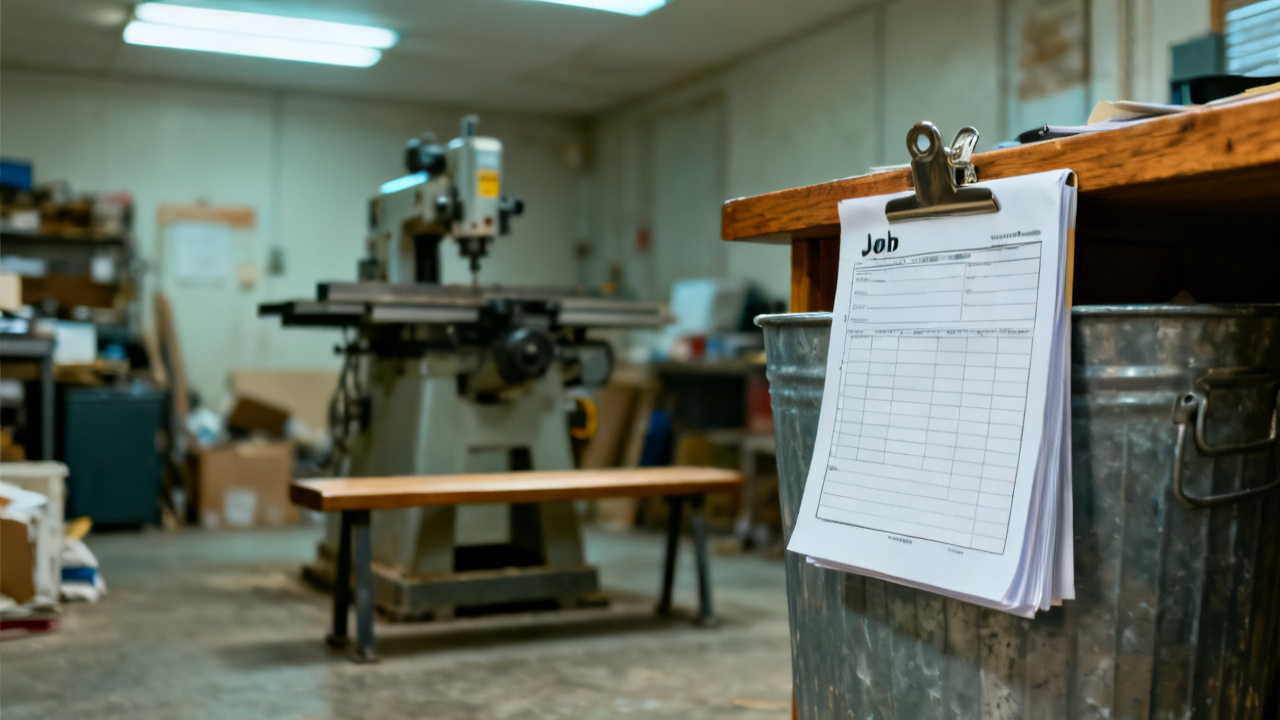
The current step is marked. You finished a different step this morning. You set the ½” spiral upcut bit in the router collet ten minutes ago, and the clamped 6061 aluminum blank sits level on the spoilboard directly under the spindle. The sheet propped on the Traveler Desk ledge has two highlighted lines that look almost identical at first glance, but mixing them up scraps $70 worth of material per part and pushes the 12-part batch deadline back two full days. You lean in to trace the fine print under each line to confirm you are referencing the correct parameter set before you lower the spindle.
This sheet’s Pilot Hole Route Line and Full Profile Route Line
This section of the sheet splits the router work into two sequential passes, and you are only cleared to run the first pass right now. The Pilot Hole Route Line calls for four ¼” holes drilled to a depth of 0.375” at the four marked corner points on the blank, to act as alignment guides for the second assembly step later in the run. The Full Profile Route Line calls for cutting the outer edge of the blank down to the final part dimensions, a step you only run after you complete and inspect all 12 parts’ pilot holes to confirm alignment. If you accidentally run the full profile cut first, you lose the reference marks you need to place the pilot holes in the exact required position, and you cannot salvage the blank even if you re-drill the holes later. You run a quick test on the scrap aluminum piece you keep at the bench to confirm the bit cuts cleanly at the listed feed rate before you start on the first production blank.

Printed notes below Pilot Hole Route Line and Full Profile Route Line
Each line has 3 small superscript numbers that link to printed notes at the bottom of this section, and you cross-reference these notes before you input any parameters into the router control panel. Follow these steps to confirm you are working from the correct line’s notes:
- Locate the superscript 1 next to the feed rate listing on the Pilot Hole Route Line, and match it to the note at the bottom of the column that specifies the feed rate is set to 120 inches per minute for aluminum only, not for the plastic test blanks you used for the setup run.
- Find the superscript 2 next to the depth listing on the Full Profile Route Line, and note that this depth only applies when you are running the second pass with the ¼” straight bit, not the ½” spiral bit you have installed right now.
- Cross-reference the superscript 3 next to the clamp placement note on both lines, and confirm that the clamp positions for the pilot hole step do not overlap with the cut path for the full profile step, so you do not have to re-clamp parts between the two steps if you mark the clamp positions on the spoilboard now.
- Scan the handwritten note scrawled in the margin next to the Full Profile Route Line that says all parts require a 0.002” finishing pass after the rough profile cut, a specification added after the initial sheet was printed last week.
You jot a small pencil dot next to the superscript 1 note to remind yourself to adjust the feed rate down if you switch to running plastic parts for a different batch later in the day.
Measured tolerance ranges for Pilot Hole Route Line and Full Profile Route Line
Each line lists a separate tolerance range for critical measurements, and you reference these ranges when you run your in-process spot checks every three parts. The Pilot Hole Route Line lists a position tolerance of ±0.015” for the center point of each hole, relative to the pre-scribed marks you added during the marking step you completed this morning. The Full Profile Route Line lists a position tolerance of ±0.005” for the outer edge of the part, relative to the center point of the top-left pilot hole, a tighter tolerance because the outer edge mates directly to a matching plastic housing in the final assembly. Illustrative example: a 0.012” offset between the pilot hole center and the marked guide mark on the blank counts as a passing measurement for this step, so you do not need to scrap the part or adjust the router settings if you get that reading on your caliper. You keep a small spiral notebook next to the control panel to log any out-of-tolerance readings you find during spot checks, and you flag the line with a small check mark next to the tolerance field every time you confirm a part passes inspection. If you find three consecutive parts that fall outside the tolerance range for the pilot holes, you pause the run immediately to check the collet tightness, bit wear, and spoilboard level before you run any additional parts.
Post-run signoff fields for Pilot Hole Route Line and Full Profile Route Line
This is the section you interact with the next time you open this same sheet, after you have run all 12 parts through the pilot hole step and completed your final spot checks for the batch. The Pilot Hole Route Line has a single signoff field for you to print your name, date the entry, and note the number of passing and scrapped parts from the batch, so the next operator who picks up the sheet knows they can move forward with the full profile cut step. The Full Profile Route Line has two separate signoff fields: one for the operator who runs the rough profile cut, and one for the operator who runs the final finishing pass, so you can track who completed each step if any quality issues arise later in the production process. You do not fill out the signoff fields for the Full Profile Route Line right now, even if you plan to run that step yourself later in the week, because the next operator needs to confirm that all pilot hole checks are complete before they move forward with their work. If you scrapped any parts during the pilot hole step, you attach the scrap tag for each part to the back of the sheet with a piece of masking tape, so the production scheduler can adjust the batch count and order replacement material if needed before the full profile step begins. You double-check that the batch number printed at the top of the sheet matches the batch number etched into the corner of each blank before you sign off, to make sure you are not marking the wrong sheet complete if you have multiple router runs going at the same time. You also add a small sticky note to the top of the sheet if you notice any unusual bit wear during the run, so the next operator knows to inspect the bit before they start the full profile cut and avoid unexpected tool breakage mid-run.