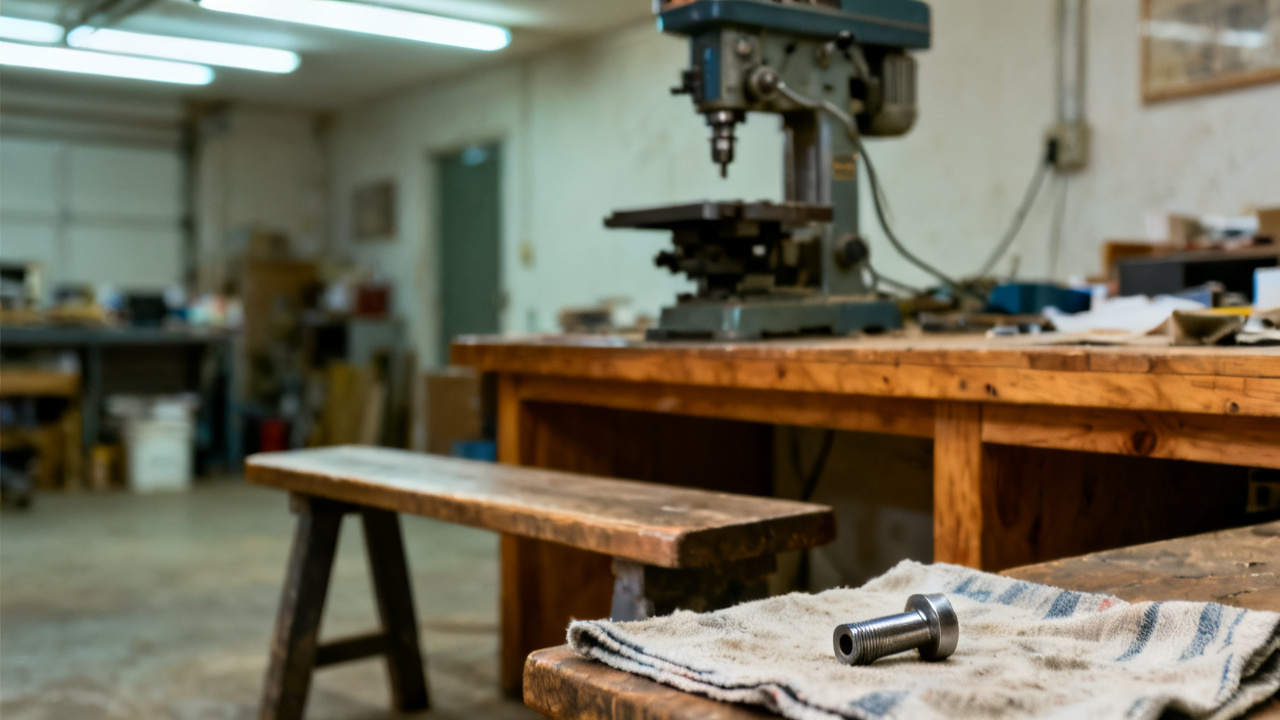
The part is at the layout table. The check sheet is still at the machine. You brush the fine, silvery aluminum swarf off the cold granite surface plate before reaching for the part, running a finger along the rough-cut datum edge to feel for any burrs that would throw off your measurements. You set the part down temporarily on the rubber mat next to the plate, so you don’t scratch the polished granite surface while you retrieve the check sheet from the mill.
How this check document aligns to your layout work
You walk back to the CNC mill 10 feet away, wiping the thin layer of semi-synthetic coolant off the edge of the sheet before tucking it into the clear poly sleeve mounted to the layout table’s side rail, where it sits at eye level for easy reference while you work. This sheet ties directly to the Revision C CAD file you pulled up on the wall-mounted tablet above the surface plate, so every mark you make cross-references to a dimension logged here, no guessing when you reference edge distances or hole center points later in the process. You don’t need to flip to any other pages for this work; every relevant callout for the first piece layout is printed here, no cross-referencing to separate spec binders mid-task that would break your focus and lead to measurement errors. You also don’t need to print any additional copies of this sheet, as the one in your hand is the only official reference for this first piece run, and all edits and notes will be logged directly on it for future reference.
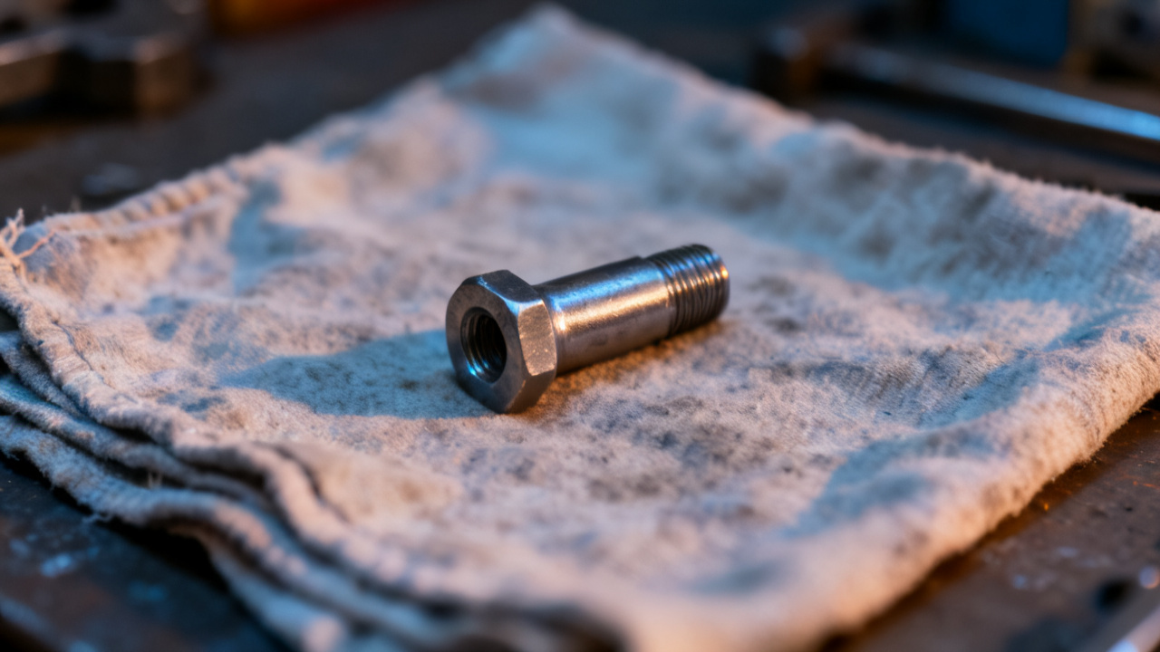
Baseline marks you confirm before scribing any cut lines
First, you confirm the datum edge is free of any machining burrs left from the initial bandsaw rough cut, running a flat Arkansas stone along the edge three times to smooth any high spots that would create a gap between the part and the 1-2-3 block you use as a stop. You then line the part up against the hardened steel 1-2-3 block clamped to the left edge of the surface plate, holding a piece of standard 20lb copy paper between the part and the block to test for gaps; if the paper slides freely anywhere along the edge, you re-stone the datum and re-test until the paper catches uniformly across the full length of the part. You zero out your digital height gauge to the surface plate before taking your first measurement, and cross-check the readout against a calibrated 6 inch gauge block to confirm calibration is within spec before you make any permanent scribe marks on the part. If you spot any deviation larger than 0.001 inches on the gauge check, you swap out the height gauge for the backup unit stored in the cabinet under the Traveler Desk, running the same calibration check again before proceeding.
Tolerance bands this document maps for each layout feature
Every layout point you mark on the part has a pre-defined tolerance band listed on this sheet, so you know exactly how much variation is acceptable for each feature before you scribe any lines. Illustrative example: the 0.375 inch H1 through hole feature has a total tolerance window of 0.004 inches, so you don’t need to flag a mark that falls within that range even if it sits slightly off the exact nominal dimension. You reference the table below for every feature you mark, checking the measurement against both upper and lower tolerance limits before you make a permanent scribe mark on the part face:
| Feature ID | Nominal Dimension | Upper Tolerance | Lower Tolerance | Verification Method |
|---|---|---|---|---|
| H1 (through hole) | 0.375 in | +0.003 in | -0.001 in | Height gauge + edge scribe |
| S1 (slot edge) | 2.125 in from datum A | +0.005 in | -0.002 in | Dial caliper cross-check |
| C1 (counterbore lip) | 0.625 in diameter | +0.004 in | +0.001 in | Digital micrometer |
| D2 (mounting hole center) | 1.750 in from datum B | +0.002 in | -0.002 in | Coordinate scale overlay |
Each line item corresponds to a highlighted mark on the printed CAD snippet on the back of this sheet, so you can cross-reference the ID number directly to the location on the part to avoid mixing up similar features across the part face. You mark each verified dimension with a small pencil check next to the feature ID on this sheet as you go, so you don’t re-measure the same feature twice if you step away from the table mid-task to assist with another machine setup. If a measured dimension falls outside the listed tolerance band, you circle the feature ID in red and jot the measured value next to it before moving to the next feature, no need to halt work entirely until you’ve checked all layout points to get a full picture of any stock variation.
Real-time notes you can log directly on this form as you work
You don’t need to use a separate notepad for any observations you make during layout; all notes can be written in the blank 2-inch right-hand margin of this sheet, as long as they are legible enough for the machinist running the full production run to read later. Common notes you might add include burr locations that need to be removed before secondary machining, slight warping on the raw extruded stock that requires adjusting cut depths for the full run, or hole positions that can be shifted slightly to avoid a visible silicate inclusion in the material that would weaken the final part. You can also cross out any dimension that is not applicable to this specific first piece run, drawing a single thin line through the line item and writing “N/A” next to it along with your initials to confirm you intentionally skipped that measurement for a valid reason. If you need to adjust a tolerance for a non-critical feature to account for raw stock variation that is within the incoming material spec, you write the new tolerance band next to the original, then leave a short note explaining the adjustment so the quality team can review it during sign-off without needing to track you down for clarification.
First piece sign-off review you complete with this sheet
You pull this sheet out again the next business day after you finish the layout, once the first fully machined piece comes off the mill for final inspection, to cross-reference every mark you made to the final part dimensions. You line up the layout scribe marks on the retained first piece blank with the measured dimensions from the final machined part, confirming that every cut falls within the tolerance bands you mapped during the initial layout work. If all dimensions match the approved specs, you sign and date the bottom of this sheet before passing it to the production lead to approve the full 500-piece production run. If some dimensions fall outside the expected range, you use the notes you logged during layout to trace the source of the deviation, whether that’s a misaligned datum edge during setup, a calibration drift on the height gauge, or a slight shift in the stock during the first machining pass. You don’t file this sheet away until the full production run is complete and the last part passes final inspection, as it serves as the official reference point for any adjustments that need to be made to the machining program mid-run to account for unexpected material variation across the batch of raw stock.